SysML + MBSE Training & Certification
Please contact us with your constructive ideas to correct and improve this section.
SysML & MBSE Trainers - USA / North America
PivotPoint Technology
Agile MBSE™ + SysML v1 & v2 Custom Training & Certification —
Tool-ind. or w/ Cameo, MagicDraw, CATIA Magic, Sparx EA, etc.
Live Expert Virtual Training in North America, EU & Japan during Local Work Hrs
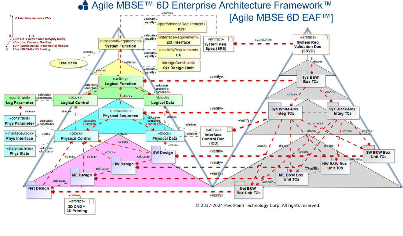
PivotPoint presents a comprehensive training and certification program in both Systems Modeling Language (OMG SysML™) and Agile Model-Based Systems Engineering™ (Agile MBSE™), skillfully blending the best practices of Agile Engineering with MBSE. The inclusive MBSE curriculum has been meticulously designed by Cris Kobryn, the founder of PivotPoint, famed for his instrumental role in the formation of UML v1, UML v2, and SysML architecture modeling language specifications. Cris, renowned for his guidance to successful MBSE teams globally, has been recognized with the prestigious INCOSE Outstanding Service Award in 2006 and the SD Times 100 "Modeling" category award in 2007 on behalf of the SysML Partners consortium.
TOOL-INTEGRATED & TOOL-INDEPENDENT CUSTOM TRAINING:
PivotPoint's MBSE + SysML + optional SysML Tool course training is designed with flexibility in mind, comprising adaptable learning modules tailored to the unique needs of your MBSE team and project. They provide both tool-independent and tool-integrated course options, encompassing tools such as Cameo, MagicDraw, CATIA Magic, Sparx EA, and other SysML-compliant tools available upon request. Clients who choose Cameo/CATIA Magic integrated training can choose between OMG SysML v1.x or v2 standards.
MBSE Expert Trainers and Coaches with 10+ years professional experience that are certified proficient in:
- SysML Architecture, Analysis & Design patterns
- Leading MBSE SysML ModSim tools (Cameo/MagicDraw, Sparx EA; others available on request)
- Agile MBSE™ processes and methods
SysML Training Program
InterCAX and Georgia Tech jointly offer a SysML quick start training program for professionals wanting to learn about MBSE.
System Modeling with SysML & OCSMP Model User Exam Preparation
SysML modeling training course offered separately from OCSMP exam preparation.
Fundamentals of Systems Modeling
Systems modeling class taught using the SysML language.
Systems Engineering with SysML and UML Training Bootcamp
SysML/UML training course is an extension to a Systems Engineering training course.
The Systems Modeling Language (OMG SysML)
SysML modeling training course.
OCSMP Accelerator / SysML Training Course
SysML modeling and OCSMP certification training course.
SysML & MBSE Trainers - Europe/Middle East/Asia (EMEA)
Custom MBSE + SysML Training & Certification
Basic, Intermediate, and Advanced Model-Based Systems Engineering (MBSE) + SysML training and certification based on flexible learning modules that can be tailored for team and project needs. Training is available via Live Virtual (Online) Classrooms and Onsite, and is offered in tool-independent and tool-customized versions. Tool-customized versions support popular SysML modeling tools (Enterprise Architect, Cameo, MagicDraw, Rhapsody; other tools available upon request).
[Company is USA-based but offers onsite training in Europe & Japan.]
System Modeling with SysML & OCSMP Model User Exam Preparation
SysML modeling training course offered separately from OCSMP exam preparation.
[Company is UK-based.]
Systems Engineering using SysML
SysML course that covers the techniques and methodologies of Systems Engineering in a real-time embedded environment using SysML.
[Company is UK-based.]
Systems Engineering with SysML
SysML seminar that introduces object-oriented analysis and design techniques using SysML.
[Company is Germany-based.]
Modeling Complex Systems Using UML 2 and SysML
Course explains how to use UML 2 and SysML its variant for modeling complex systems.
[Company is France-based.]
Systems Engineering with SysML
Course explains a systems engineering approach with SysML that complies with the technical processes of the ISO 15288 standard.
[Company is France-based.]
TOGAF and ARCHIMATE are trademarks of The Open Group.
ENTERPRISE ARCHITECT is a trademark of Sparx Systems Pty Ltd. MAGICDRAW and CAMEO are trademarks of No Magic, Inc. RATIONAL RHAPSODY is a trademark of IBM.
All other trademarks are the property of their respective owners.
